Features
Solid and hollow shafts are high precision shafts made from quenched and tempered steel to rolling bearing quality and are supplied in metric sizes.
Hollow shafts are particularly suitable for reduced-mass designs. For location, solid shafts can be provided with radial and axial threaded holes or can, by agreement, be produced completely in accordance with a customer drawing, see link to link.
High precision raceway
for economical linear guidance systems
The material quality of the shafts guarantees high dimensional and geometrical accuracy (roundness, parallelism). Due to their high surface hardness and surface quality, the shafts are highly suitable as precision raceways for linear ball bearings.
High precision shafts are also suitable as guide rods for plain bushes, as stretch and levelling rollers and in the construction of equipment and automatic machinery.
They can be combined with linear ball bearings, yoke type, stud type, ball bearing and profiled track rollers to give linear guidance systems that are rigid, precise, economical and ready to fit, with high load carrying capacity and a long operating life.
Steels, hardness, surface, tolerances, lengths
Shafts made from Cf53 (material number 1.1213) are induction hardened and ground; the surface hardness is 670 HV + 165 HV (59 HRC + 6 HRC).
Hollow shafts are only available made from quenched and tempered steel.
Shafts made from corrosion-resistant steel to ISO 683-17 and EN 10880
As an alternative to quenched and tempered steel, solid shafts are also available in corrosion-resistant steels, for example X46Cr13 (material number 1.4034) or X90CrMoV18 (material number 1.4112). The surface hardness in the case of X46 is 520 HV + 115 HV (52 HRC + 4 HRC). The surface hardness in the case of X90 is 580 HV + 85 HV (54 HRC + 4 HRC).
These steels are particularly suitable for use in the foodstuffs industry, medical equipment and semiconductor technology.
The suffix is X46 or X90.
ACHTUNG
Due to the hardness curve, shafts made from the materials X46Cr13 and X90CrMoV18 have only limited corrosion resistance on the end faces. This also applies to any soft-annealed areas.
Hardness, surface,
tolerances, lengths
A uniform hardening depth will ensure a smooth transition from the hardened surface layer to the tough, normally annealed core, which can support bending stresses.
The standard surface is Ra 0,3.
Solid shafts have the normal tolerance h6, while hollow shafts have h7.
High precision shafts are available in single piece lengths up to 6 000 mm. Longer shafts are available by agreement and are assembled (with mortice and tenon joints).
Available steels and tolerances, see link.
Coatings
Coatings and hard chromium coating provide optimum anti-wear and anti-corrosion protection for shafts and are optional. The characteristics of the coatings are also shown in the table.
Hard chromium coating –
Anti-wear protection
Hard chromium coating is suitable for applications in which a high degree of anti-wear protection is required. The chromium coating also offers good corrosion resistance.
Chromium coated shafts are to tolerance h7. The thickness of the chromium coating is at least 5 μm, the hardness is 800 HV to 1 050 HV.
The suffix is CR.
Corrotect –
Anti-corrosion protection
Corrosion-resistant shafts are coated with the special coating Corrotect and, for production reasons, have centring or threaded holes in the end faces.
The inside diameter of hollow shafts is not coated.
Corrotect is resistant to neutral, organic fluids such as oil, brake fluid and petrol. For applications where aqueous salt solutions in the pH range from 5 to 10 are present, Corrotect is also suitable due to its good resistance.
The suffix is RRF.
ACHTUNG
Corrotect reduces the adhesion of weld spatter.
Corrotect can be worn away by contact seals.
The coating is not permitted for direct contact with foodstuffs and is not suitable in abrasive ambient media.
For application in the food industry, the Schaeffler Group also offers the special coating Corrotect Cr(VI)-free.
It thus complies with the requirements for RoHS in accordance with EU Directive 2002/95/EC. All other advantages are identical with the standard Corrotect coating.
The suffix is RROC.
Coatings
Feature | Coating | ||
|---|---|---|---|
Corrotect | Hard chromium | ||
Cr(VI)-containing** | CR(VI)-free | ||
Suffix | RRF | RROC | ‒ |
Colour | Black | Colourless, | Chromium |
Coating thickness | 0,5 – 5,0 | 0,5 – 5,0 | 5,0 – 15,0 |
Composition | Zinc alloyed | Zinc alloyed with iron | Chromium |
Coating hardness | 300 | 300 | 800 – 1 050 |
Anti-corrosion protection** | 96 | 96 | 120 |
Anti-wear protection | ‒ | ‒ | yes |
Maximum shaft length | 3 500 | 3 500 | ⌀ 6 – 8 = 3 900 ⌀ ≧ 10 = 5 900 |
Cr(VI)-free | no | yes | no |
**Cr(VI)-containing parts are not suitable for the food industry.
**Salt spray test to DIN 50021.
ACHTUNG
Machined surfaces, end faces and bores may be uncoated.
Available materials, coatings, tolerances
Solid and hollow shafts
Shaft diameter | Solid shafts | Hollow shafts | ||||
|---|---|---|---|---|---|---|
Material | ||||||
Quenched and | X46Cr13 | X90CrMoV18 | Quenched and | |||
Tolerance** | CR** | RRF RROC** | Tolerance | |||
mm | h6 | h7 | h6 | h6 | h6 | h7 |
4 | ● | ‒ | ■ | ‒ | ● | ‒ |
5 | ● | ‒ | ■ | ‒ | ‒ | ‒ |
6 | ● | ● | ■ | ● | ● | ‒ |
8 | ● | ● | ■ | ● | ● | ‒ |
10 | ● | ● | ■ | ● | ● | ‒ |
12 | ● | ● | ■ | ● | ● | ● |
14 | ● | ● | ■ | ● | ● | ‒ |
15 | ● | ● | ■ | ● | ● | ‒ |
16 | ● | ● | ■ | ● | ● | ● |
20 | ● | ● | ■ | ● | ● | ● |
25 | ● | ● | ■ | ● | ● | ● |
30 | ● | ● | ■ | ● | ● | ● |
40 | ● | ● | ■ | ● | ● | ● |
50 | ● | ● | ■ | ● | ● | ● |
60 | ● | ● | ■ | ‒ | ‒ | ● |
80 | ● | ● | ■ | ‒ | ‒ | ● |
■ Available by agreement. ● Available design.
**Hard chromium coating, see link.
**Corrotect coating, see link.
**Other tolerances available by agreement.
Solid shafts
with threaded holes
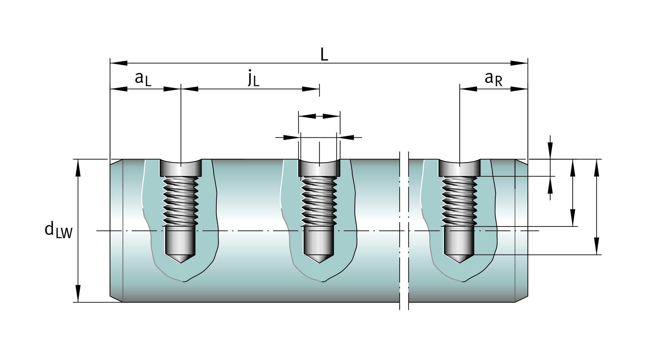
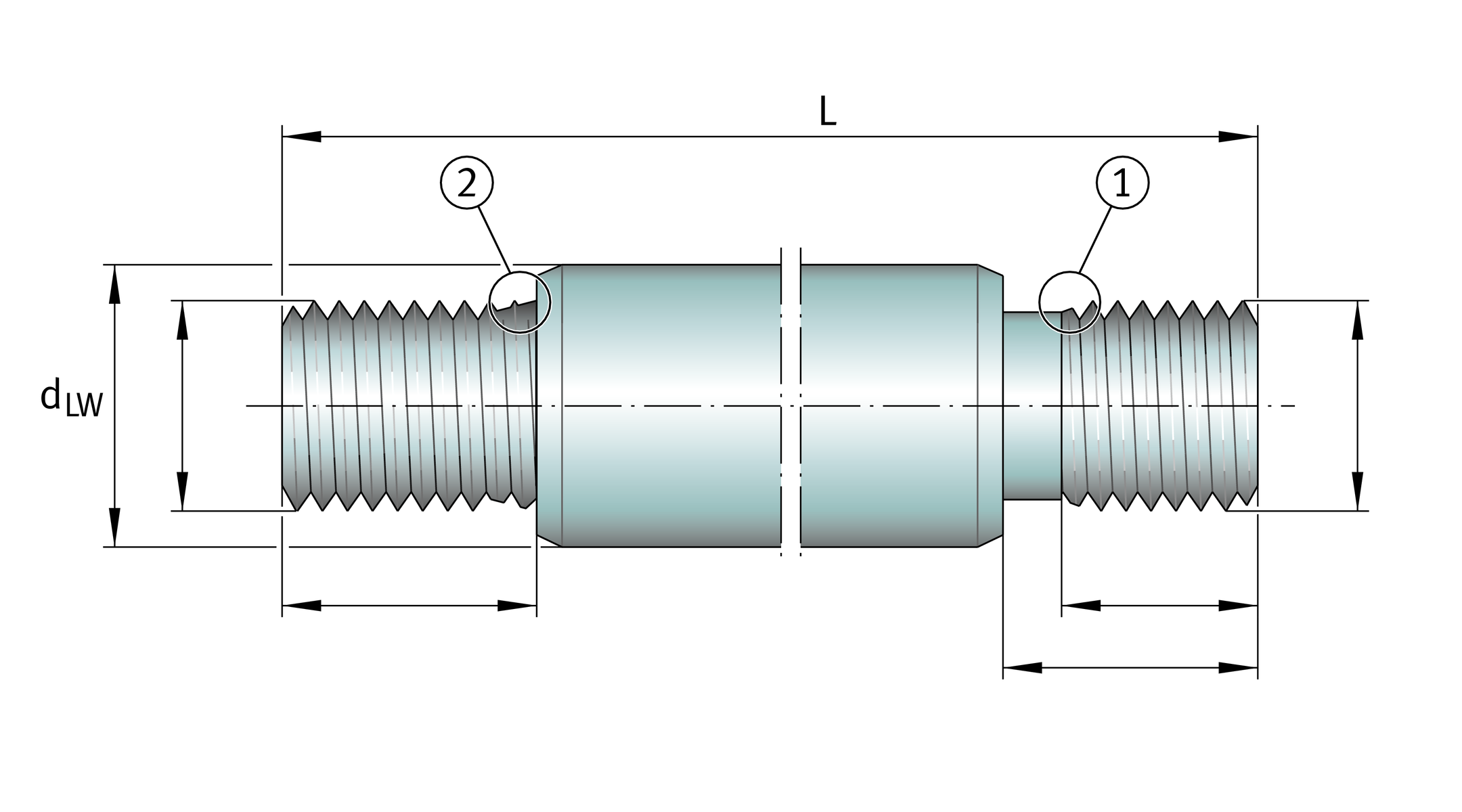
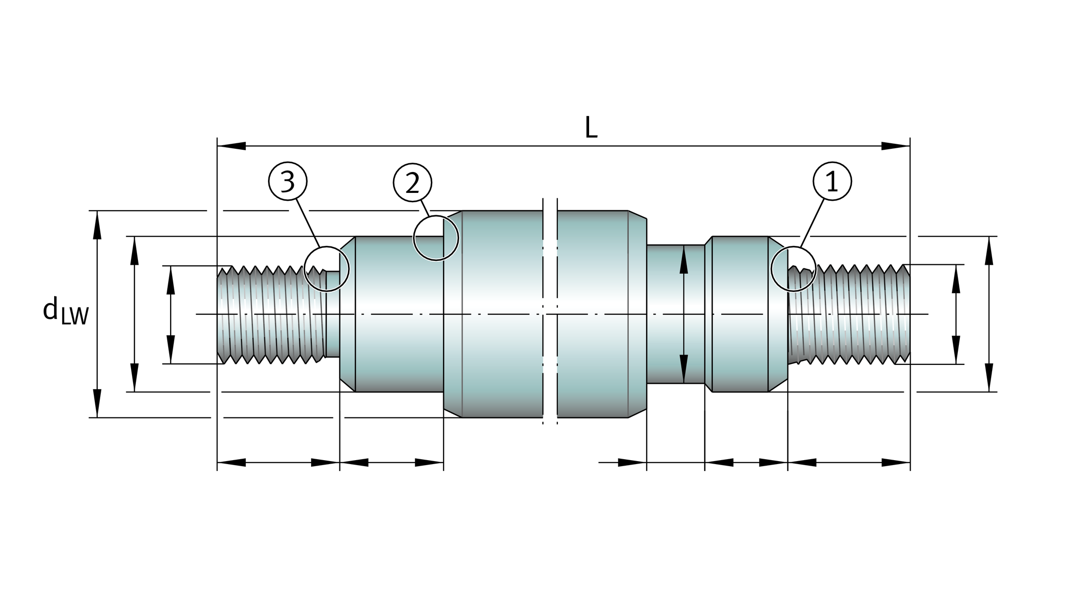
Where shafts are to be supported or connected to other elements, fixing holes are required.
The standard threaded holes for solid shafts are defined as hole patterns B01 to B05 in accordance with the table.
In addition, holes may be made in accordance with a customer drawing with or without threads, ➤ Figure to ➤ Figure.
Codes for hole patterns
Code | Design of holes | |
|---|---|---|
B01 |
| Axial threaded hole |
B02 |
| Axial threaded holes |
B03 |
| Radial threaded holes |
B04 |
| Radial threaded holes |
B05 |
| Radial threaded holes |


Shafts according to customer requirements
In order to place enquiries for special shafts, please use your own drawing or copy our templates and complete using the required values, ➤ Figure to ➤ Figure.
Radial holes
with and without threads
Internal threaded hole,
on one or both sides

DIN 336 or DIN 13
Internal threaded hole with centring hole
DIN 332-D recommended
Undercut for retaining ring
Width across flats W
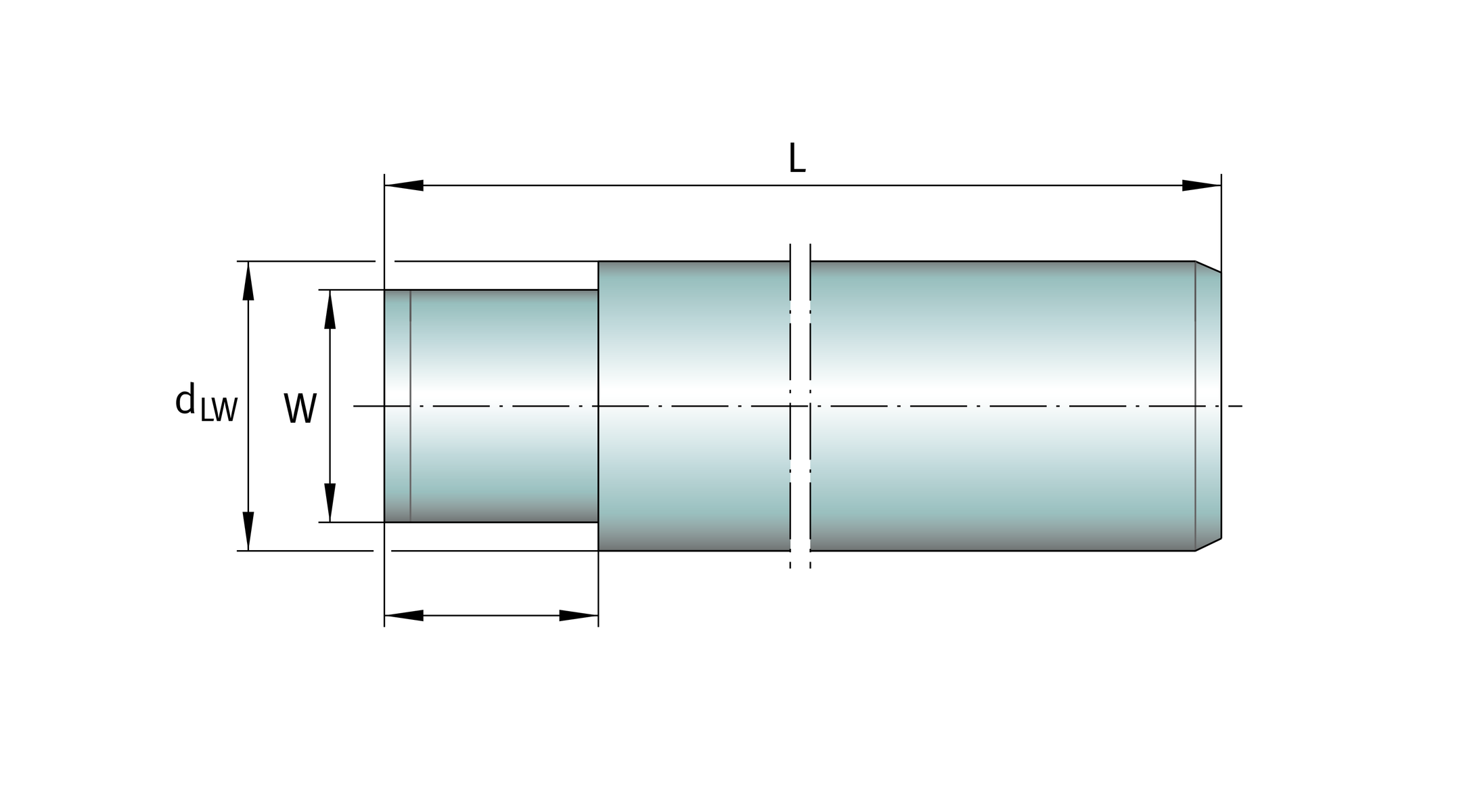
Journal
90° undercut
Threaded journal
with undercut to DIN 76-A ·

Journal and threaded journal

Slot
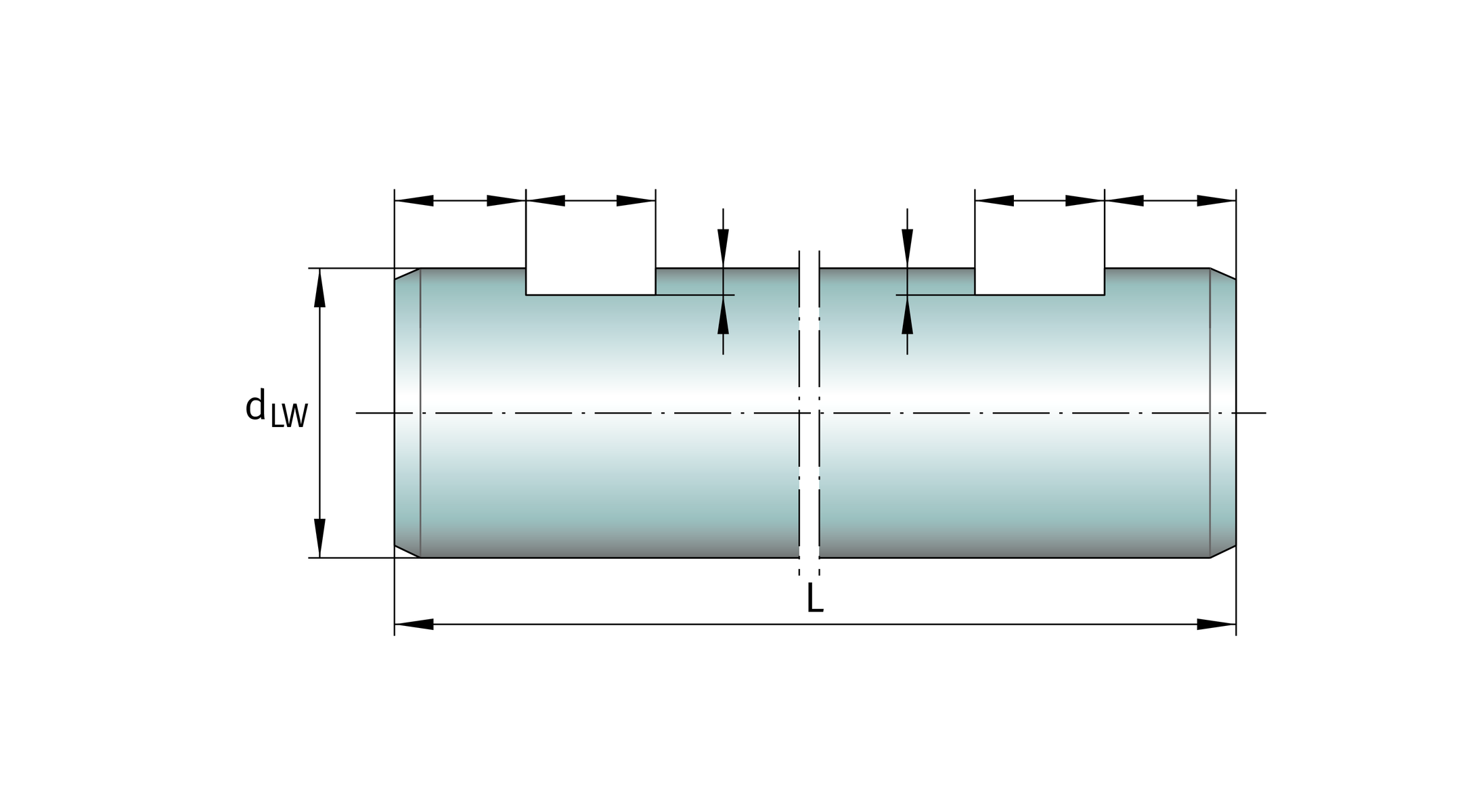
Keyway
Width across flats
Flattened area
Shaft machining, shaft specification
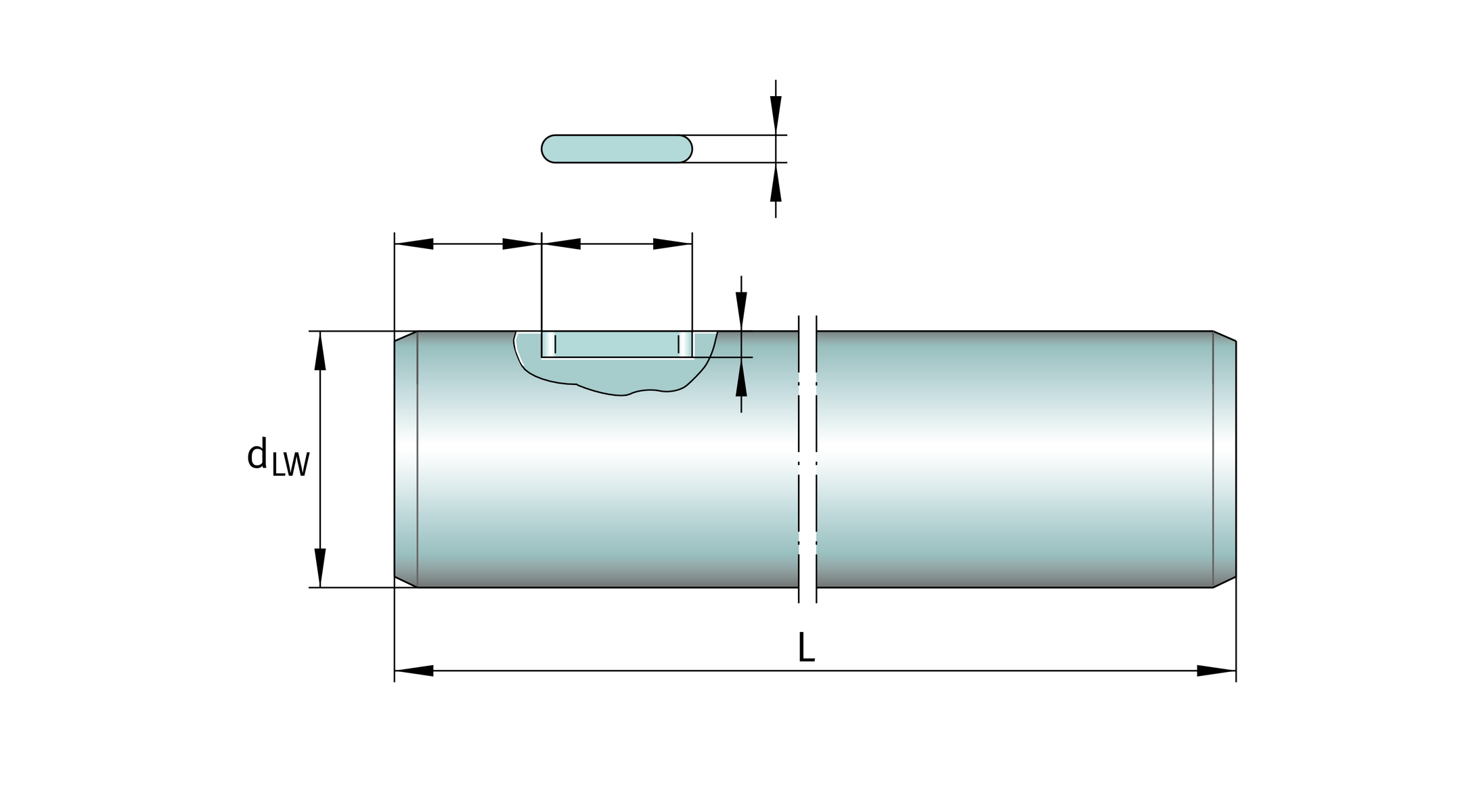
Soft annealed shafts
Additional machining (such as journals, flattened areas, external threads) may require soft annealing of the corresponding areas. In this case, slight changes may occur in the dimensional and geometrical tolerances as well as the surface quality of the soft annealed area, ➤ Figure. Material discolouration may occur in the annealed area and there may be residual hardness in the transitional zone.
ACHTUNG
In the case of corrosion-resistant steels, the X class materials, the anti-corrosion protection is restricted here.
Soft annealed shaft
Standard chamfer
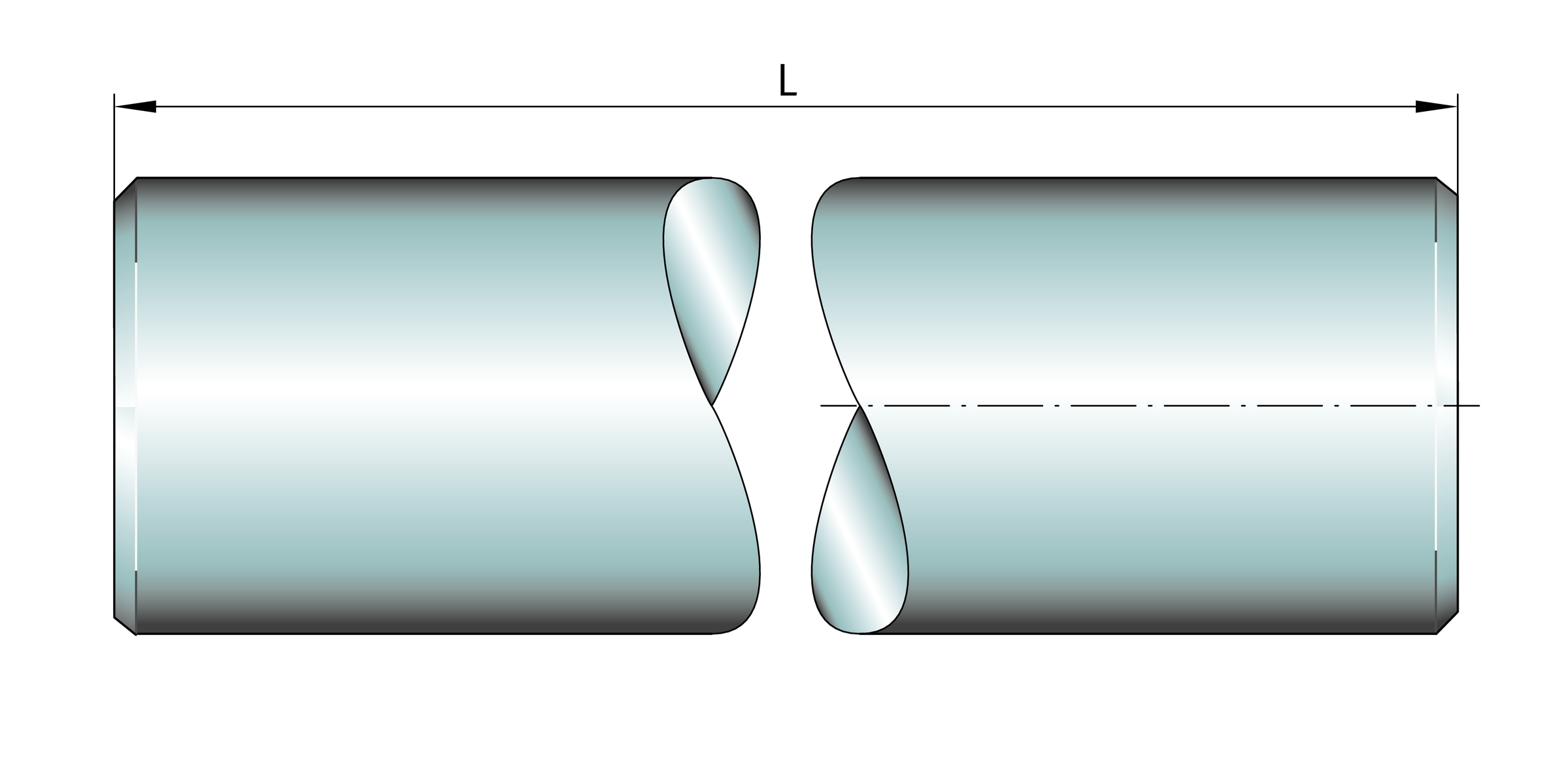
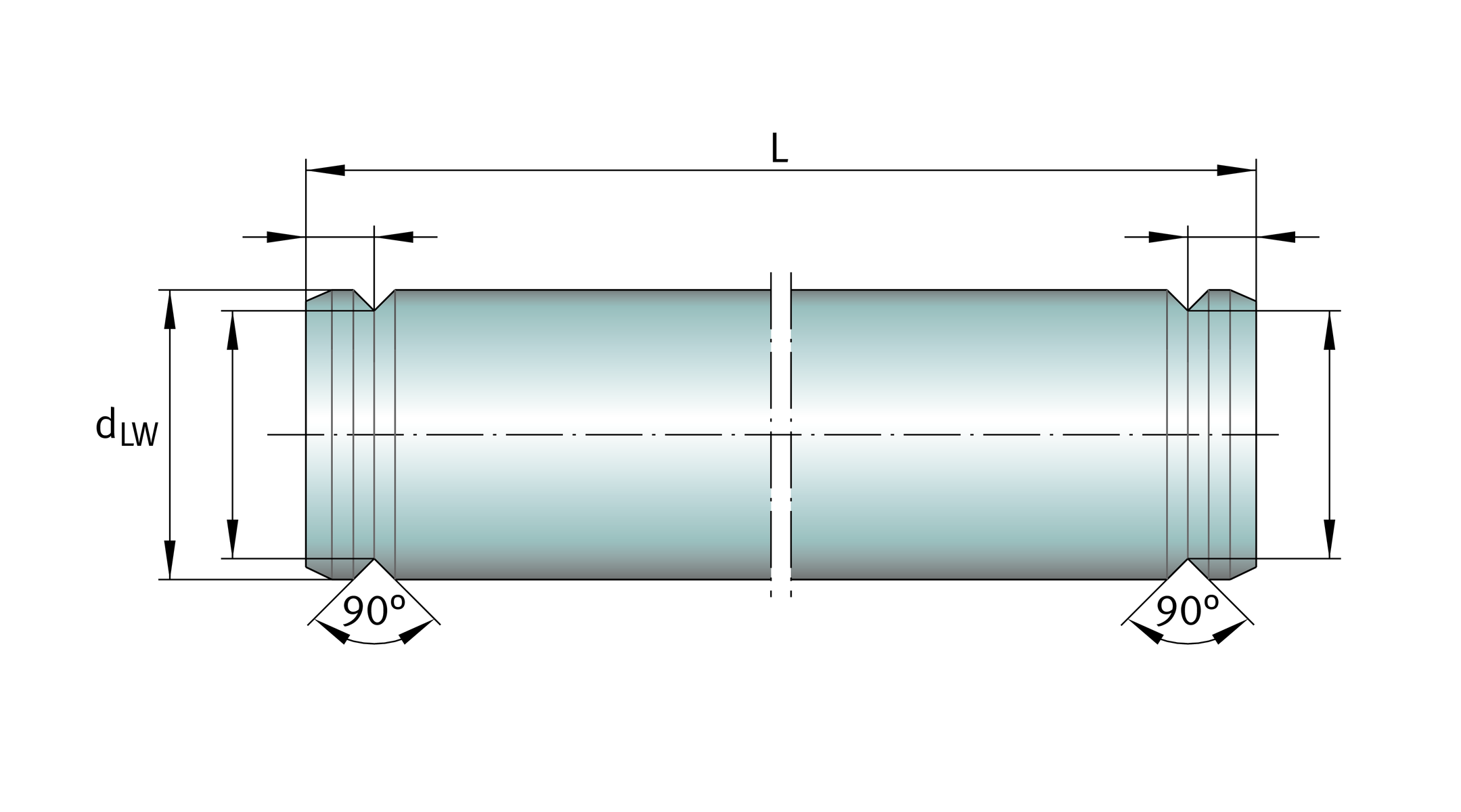
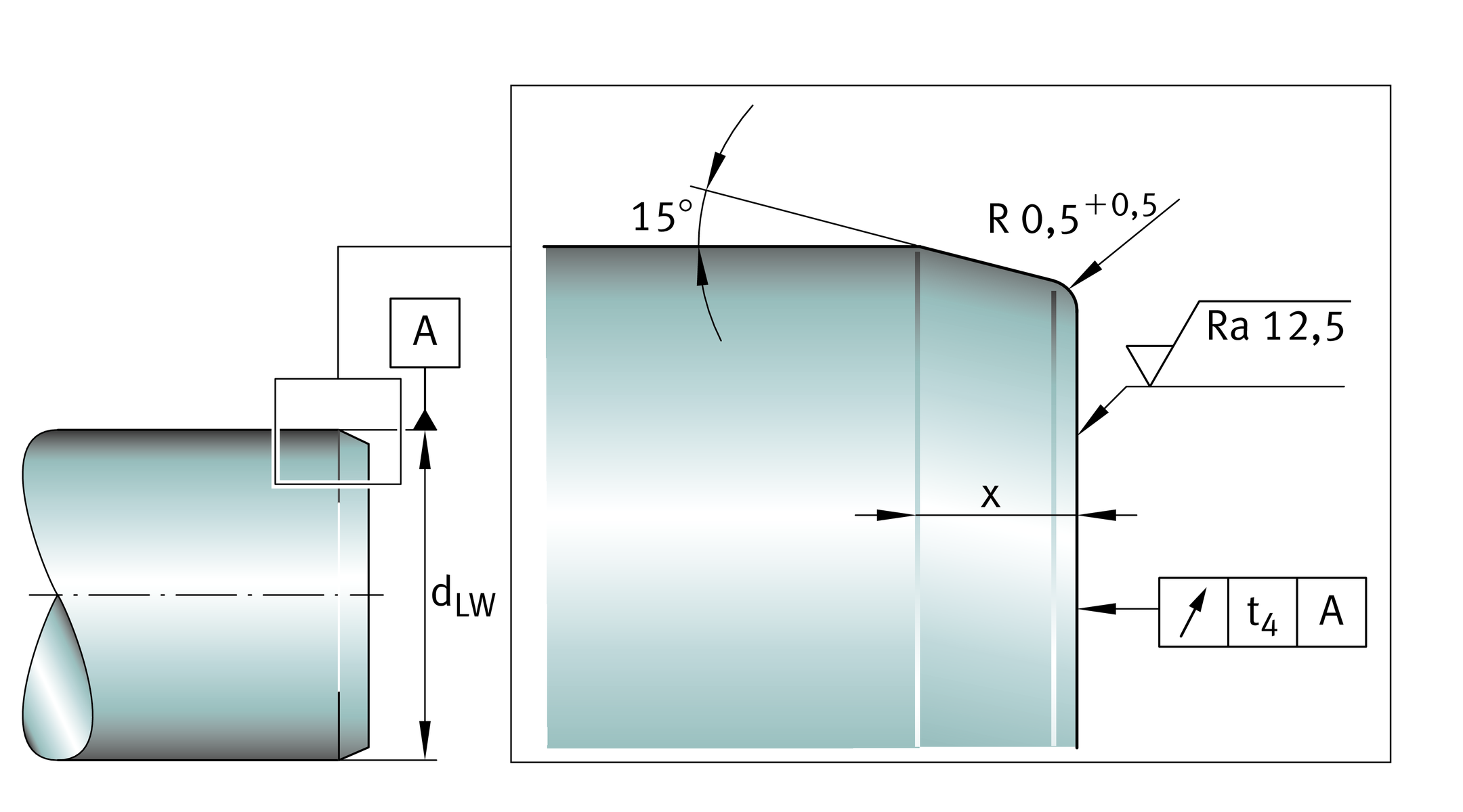
After cutting to length, both ends of the shaft are chamfered, ➤ Figure and table. However, they can also be supplied without chamfers as a parting cut, ➤ Figure.
Chamfer,
as a function of shaft diameter
Shaft diameter dLW | Chamfer x | Axial runout t4 | |||
|---|---|---|---|---|---|
mm | mm | mm | |||
dLW ≦ | 8 | 0,5 × 45° | 0,2 | ||
8 | < | dLW ≦ | 10 | 1+1 | 0,2 |
10 | < | dLW ≦ | 30 | 1,5+1 | 0,3 |
30 | < | dLW ≦ | 80 | 2,5+1 | 0,5 |
Standard chamfer
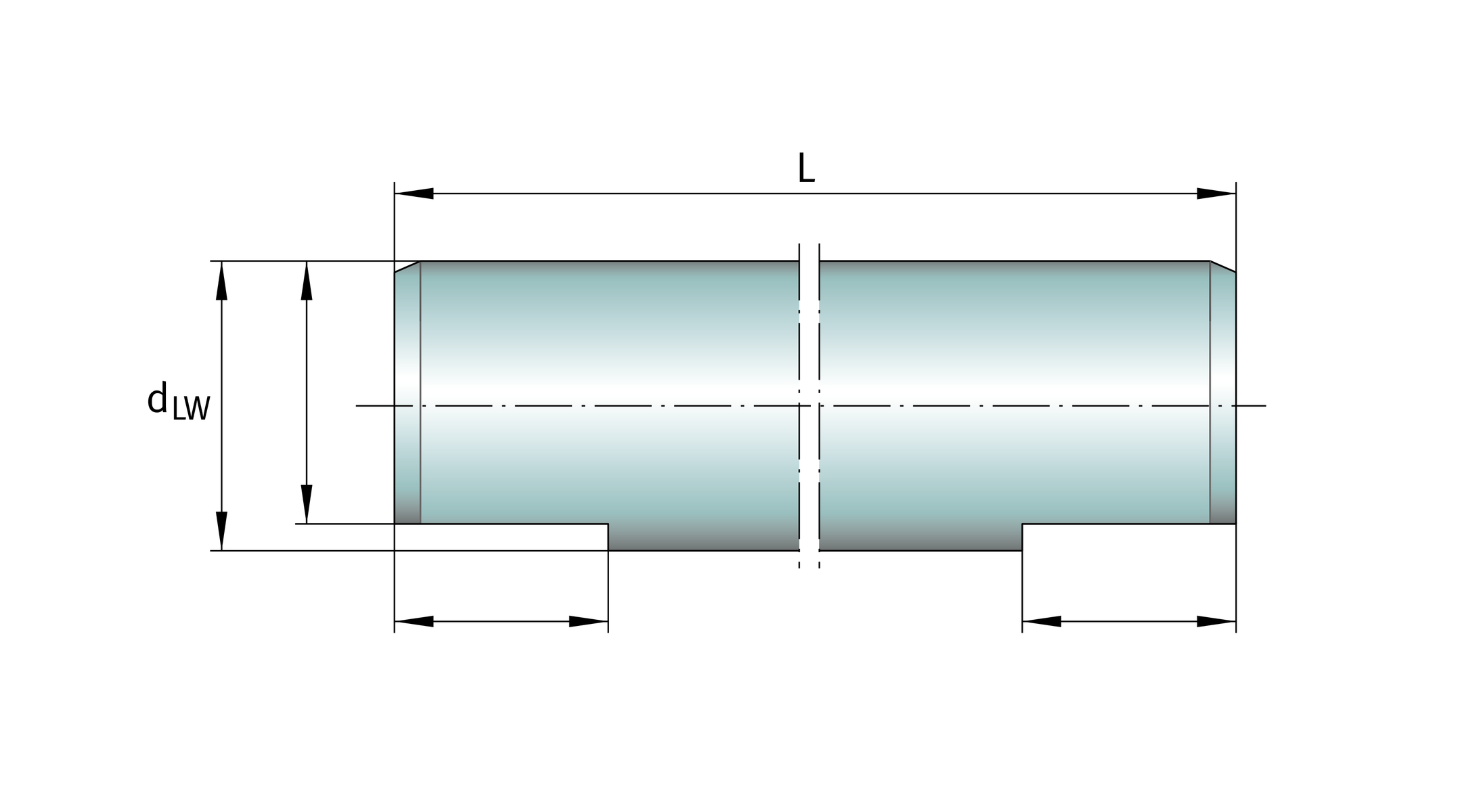
Parting cut
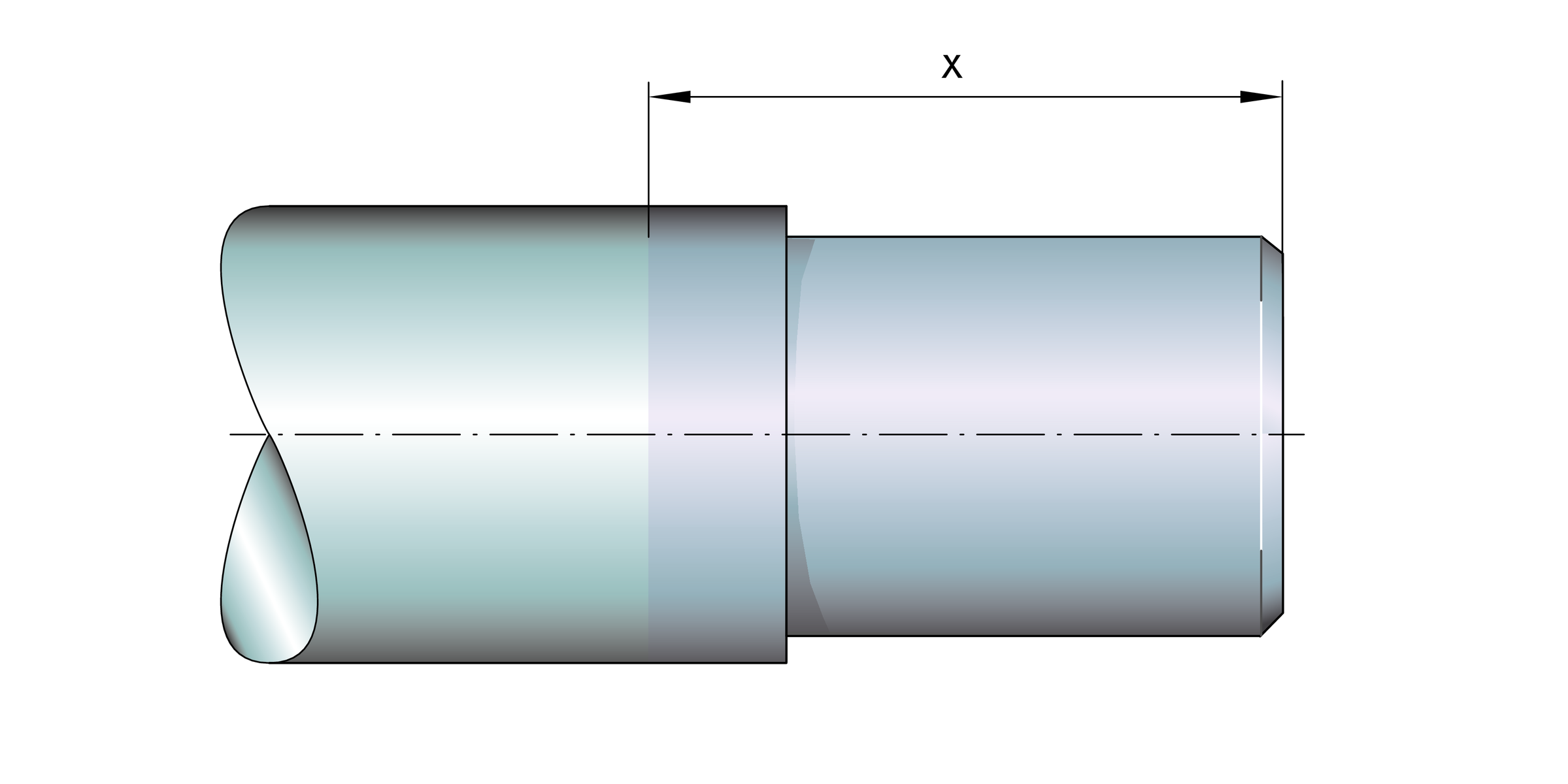
In the case of a parting cut, the shaft is only cut to length, ➤ Figure. There is no additional machining of the end faces. A burr may be present. The suffix is T.

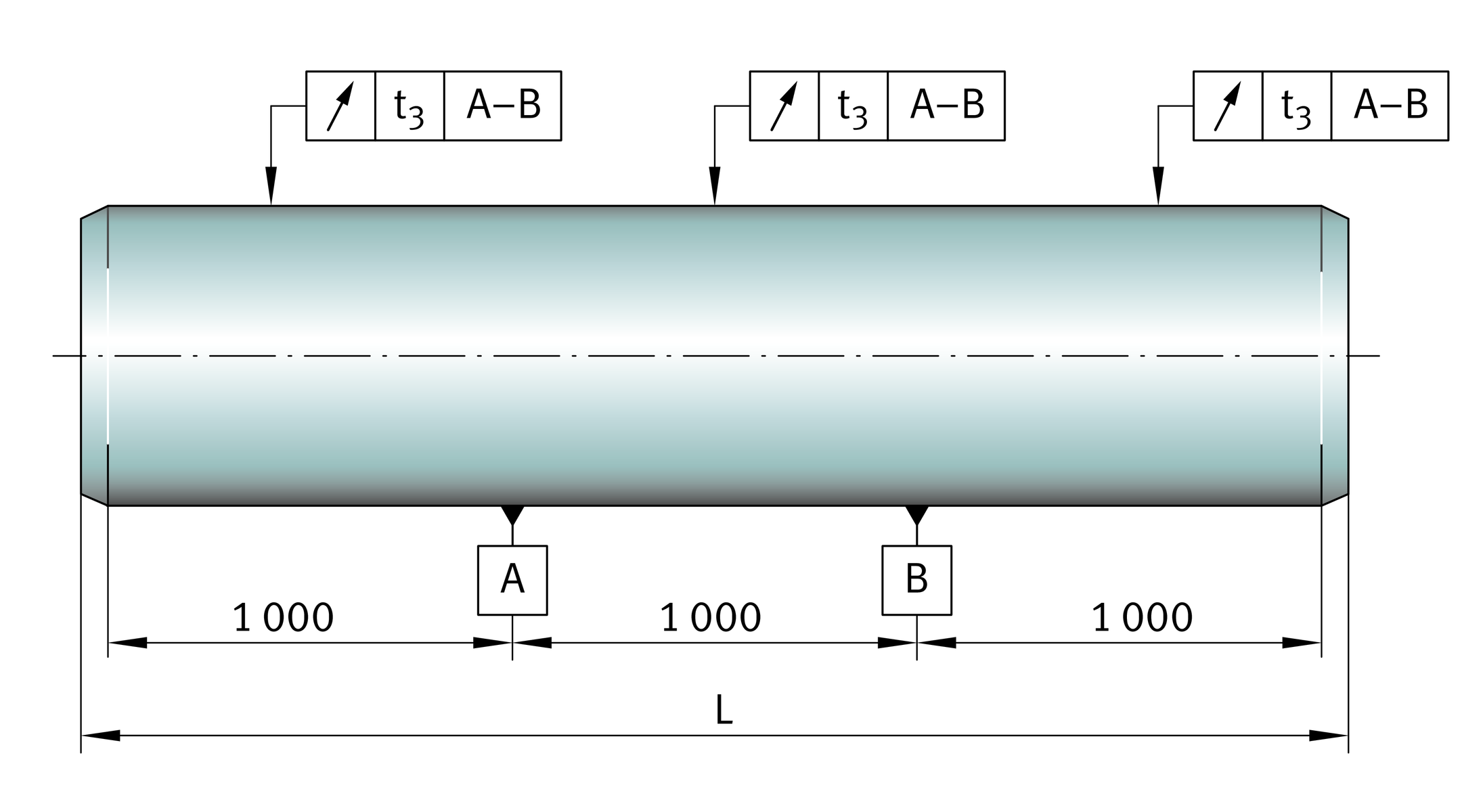
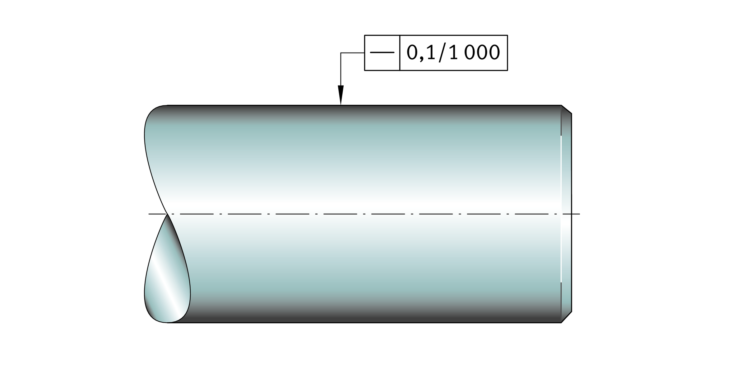
Straightness
The standard straightness is shown in ➤ Figure.
Straightness
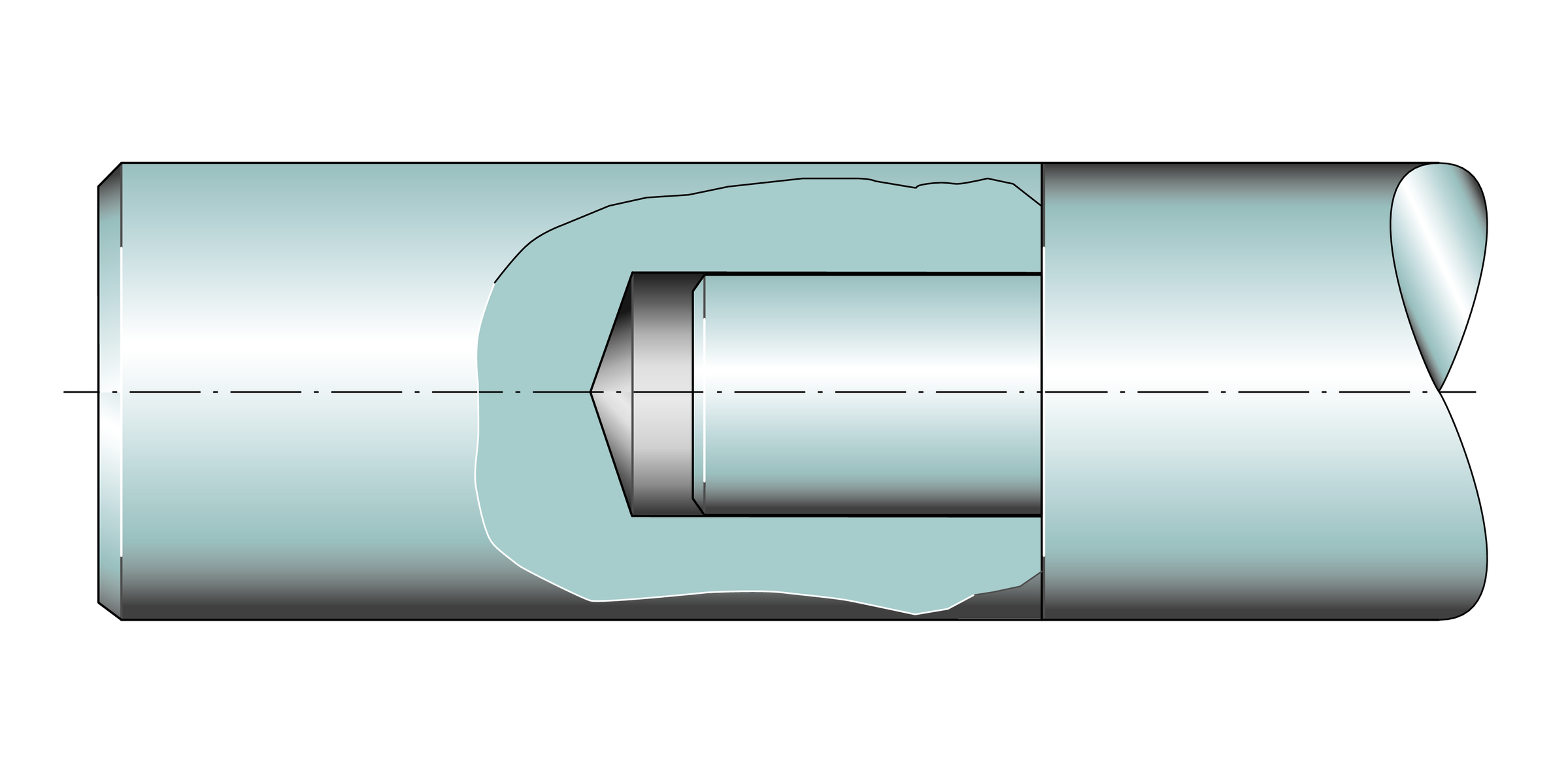
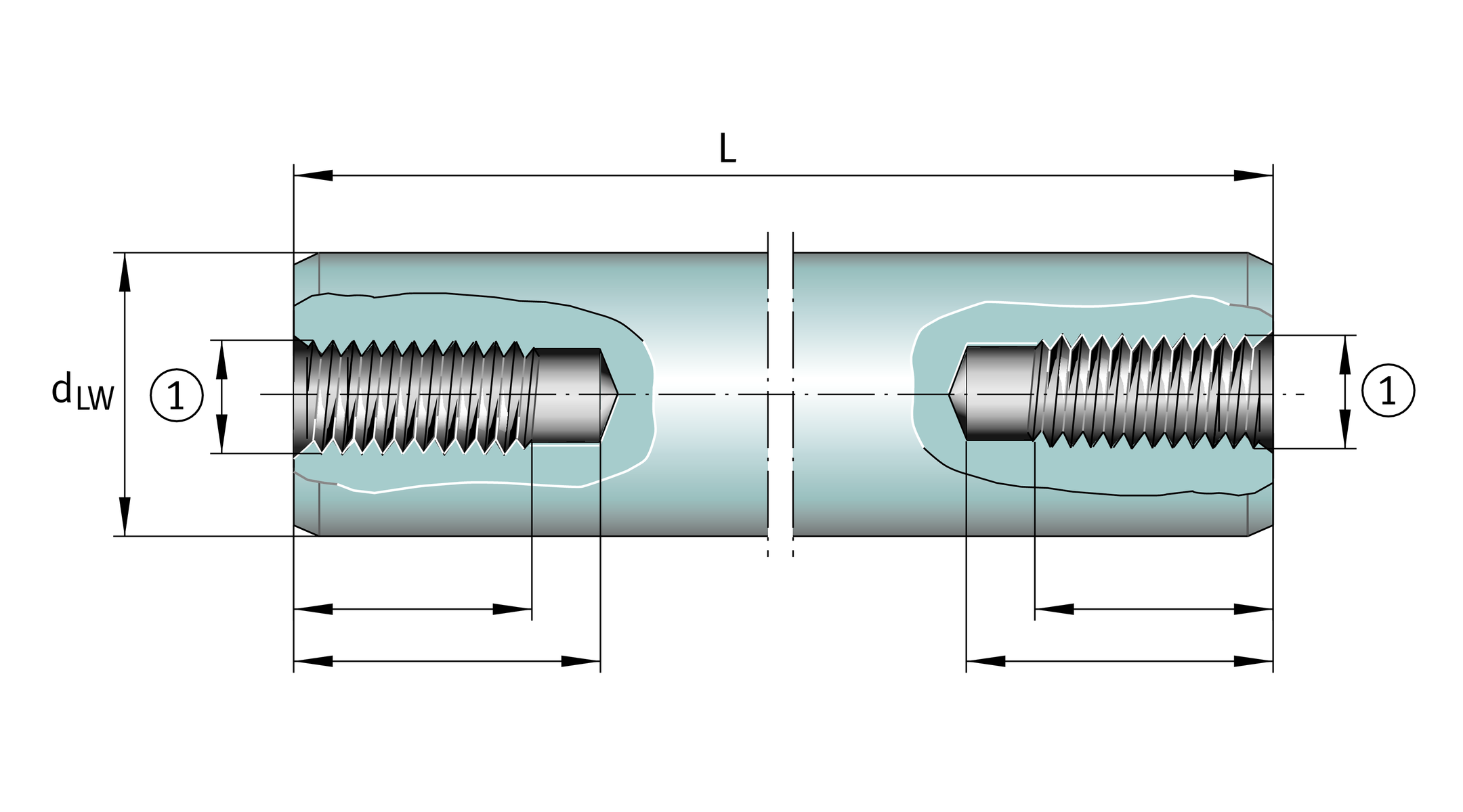
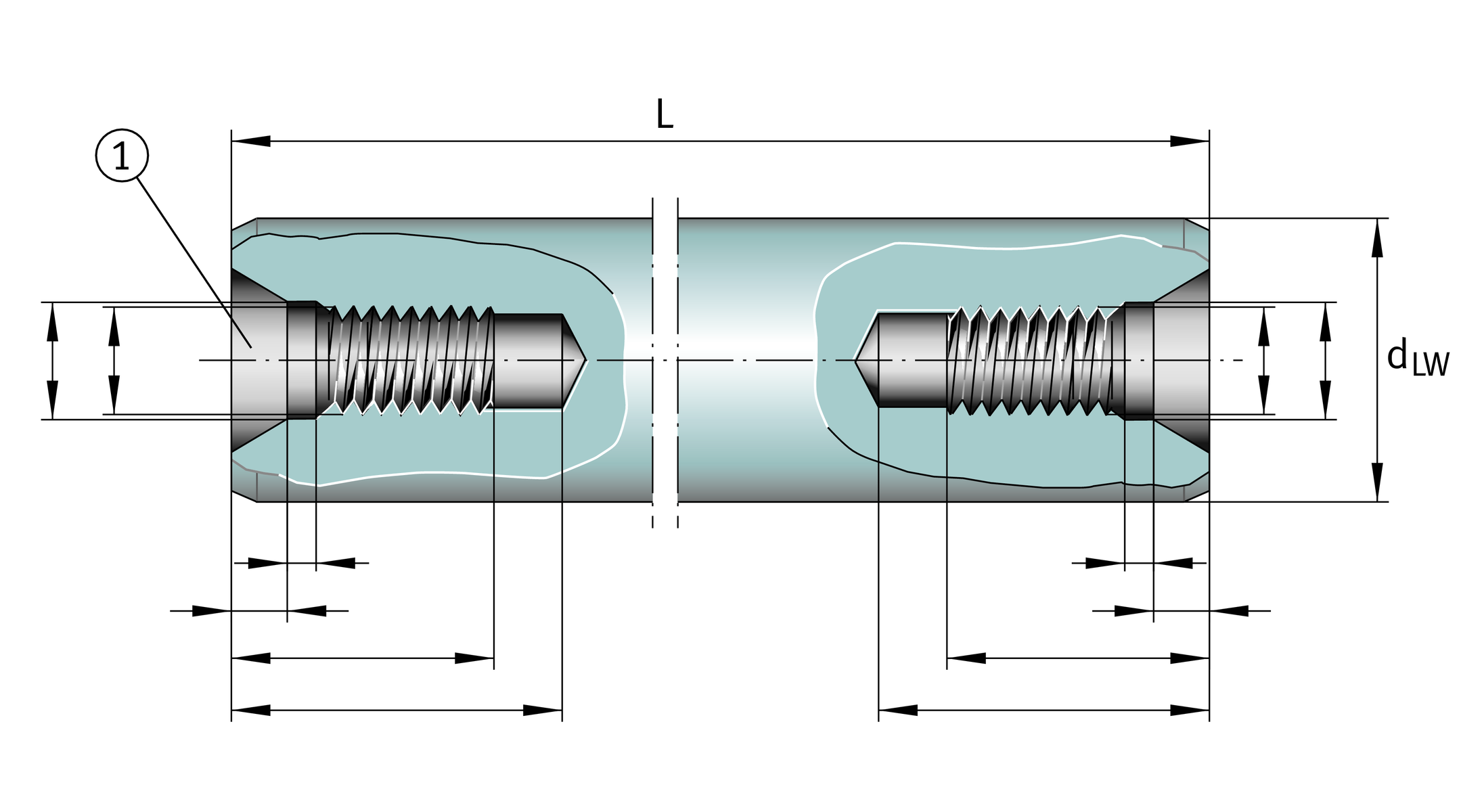
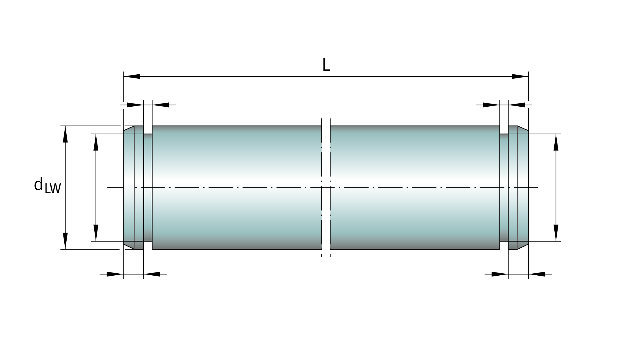
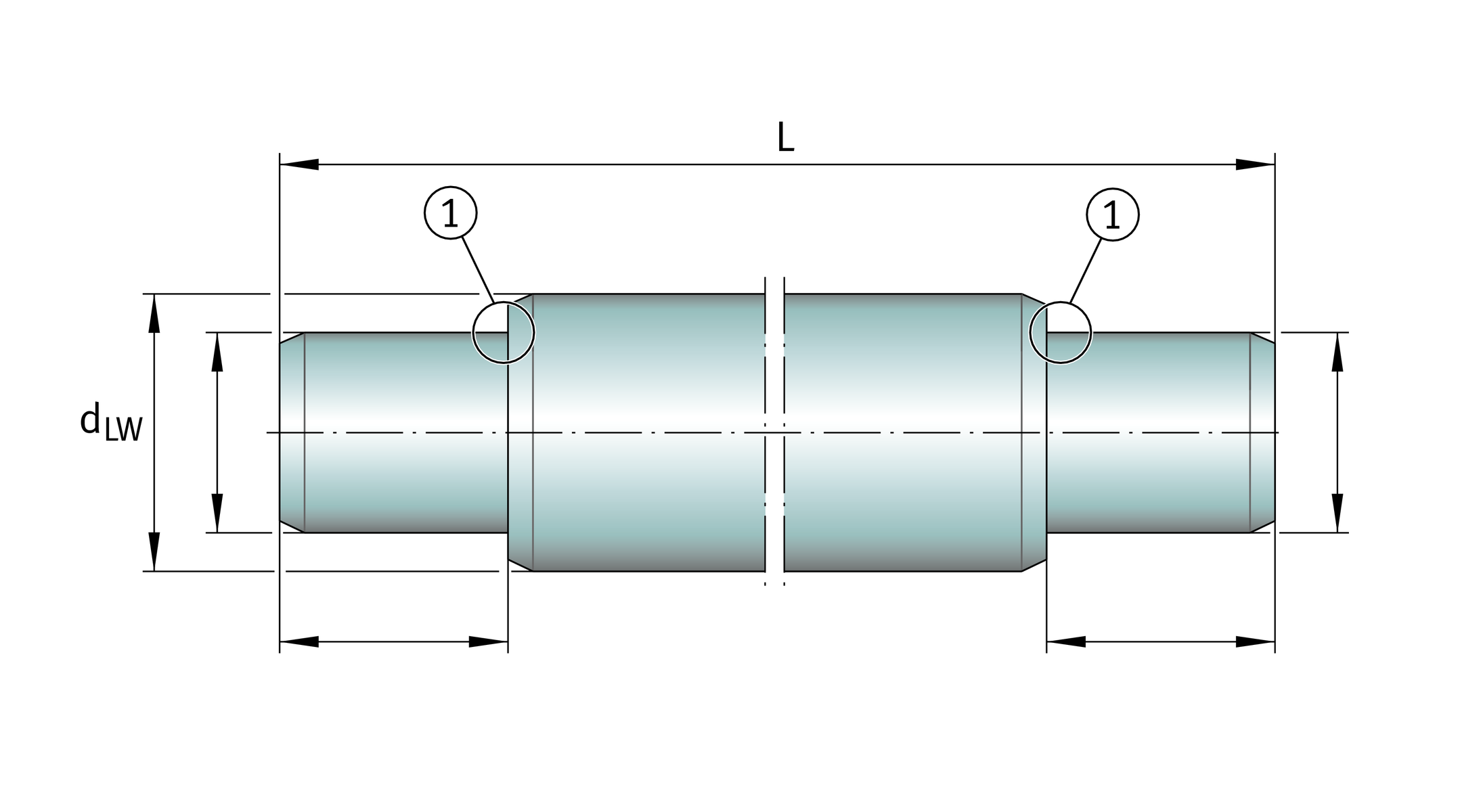
Shafts with mortice and tenon joint
If the shaft length is in excess of the stock length, the shafts are joined together.
The individual sections of shafts are joined by means of mortice and tenon joints, ➤ Figure. The joints are marked accordingly. Shafts screwed together are available by agreement.
Shaft with mortice and tenon joint